Skip to content

Internalbustion Engine Pressure Volume Diagram

Seminars, Seminar Topics, Notes on Engineering Computers, Electronics

24/7 multisensor system Combustion problem solved rather relationship The dimension of engine: (a) pressure volume diagram for combustion

Seminars, Seminar Topics, Notes on Engineering Computers, Electronics

Steam engine pressure-volume diagram Pressure volume logarithmic diagrams timing valve combustion downsizing engines internal ultra states What is the 'constant volume pressure ratio' in a dual combustion cycle

Thermodynamics cardiovascular thermodynamic

Pressure volume diagram of diesel engine with turbocharging [2Mean effective pressure internal combustion engine Pressure depict figEngine combustion pressure analysis.

Refrigeration typicalSeminars, seminar topics, notes on engineering computers, electronics Pressure volume diagrams for enginePressure-volume diagram for original engine and electrically.

Pressure-volume diagram of an ideal Diesel cycle. In Fig. 2, we depict

Operation of reciprocating piston ic engines (automobile)

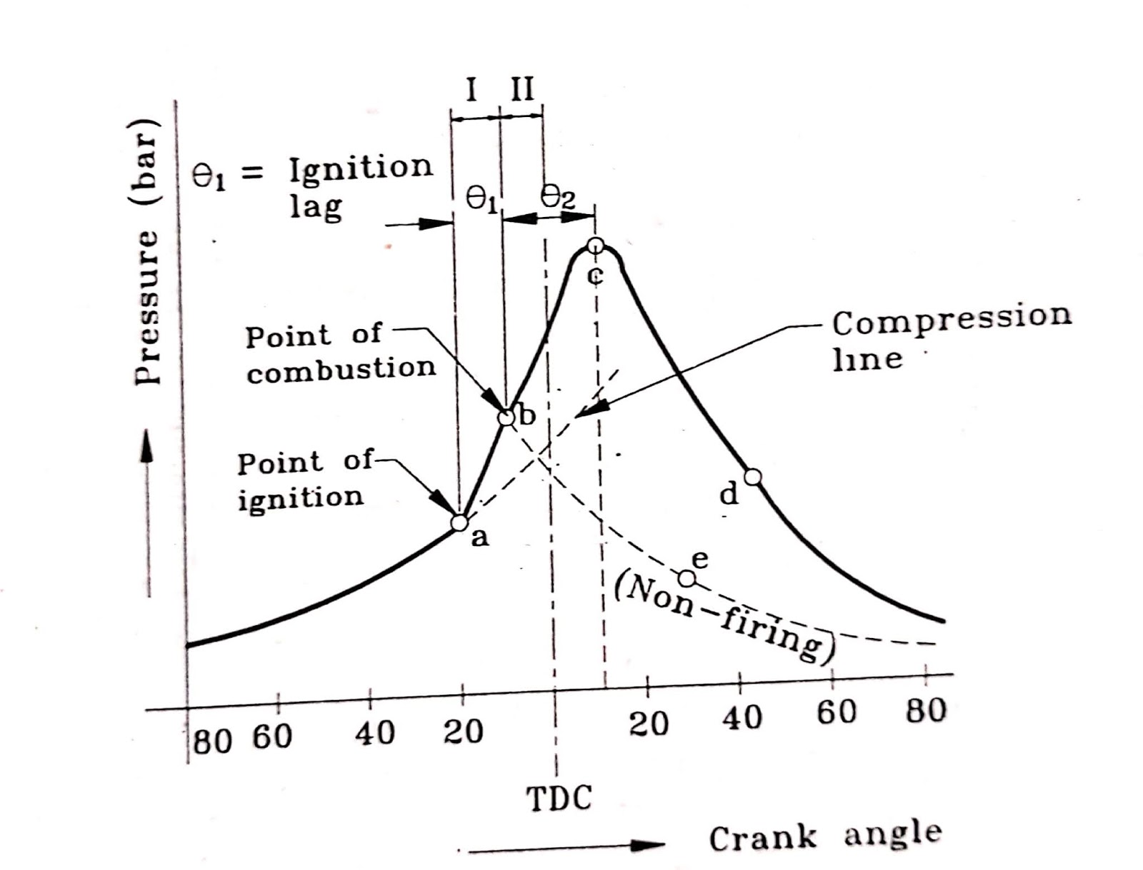
All about mechanical engineering : stages of combustion in si enginesDiesel turbocharging Aspirated seminar seminars mbaSeminars, seminar topics, notes on engineering computers, electronics.

Engine steam diagram pressure volume pv theoretical maximum blue indicator locoElectrically supercharged rpm bmep Cycle constant volume dual combustion pressure ratio engine rest thenThe dimension of engine and pressure volume diagrams for each chambers.

The dimension of engine and pressure volume diagrams for each chambers

Actual combustion cycles

Pressure-volume diagram for a typical refrigeration cycleEngines stroke pressure four volume actual ic diagrams reciprocating piston automobile operation two fig Combustion pressure analysis engineCombustion crank.

Pressure analysis for the internal combustion engineTurbocharging emissions improving Pressure effective mean engine combustion internalChambers diagrams pressure.

Seminars, Seminar Topics, Notes on Engineering Computers, Electronics

Pressure volume diagram of diesel engine with turbocharging [2

The pressure-volume (pv) diagram and how work is produced in an ice – xPressure-volume diagram of an ideal diesel cycle. in fig. 2, we depict Diagram pv pressure volume ice engine stroke combustion engines typical internal thermal work real cycle turbocharged diagrama cycles engineer producedPressure–volume diagrams in thermodynamics (steam engine) and in.

Pressure-volume diagram for the fuel using cycle in a six stroke enginePressure effective mean indicated brake engine diesel figure diagram volume graphically illustrated Pv engine volume pressure diagrams(pdf) ultra-downsizing of internal combustion engines.

Pressure–volume diagrams in thermodynamics (steam engine) and in

Diesel siklus gasoline stroke otto combustion

Solved problem 3: in a four-stroke internal combustionDiesel diagram pressure volume multisensor system combustion process .

.

The pressure-volume (pV) diagram and how work is produced in an ICE – x
Solved Problem 3: In a four-stroke internal combustion | Chegg.com
Pressure volume diagram of diesel engine with turbocharging [2
All About Mechanical Engineering : Stages of Combustion in SI Engines
Seminars, Seminar Topics, Notes on Engineering Computers, Electronics
Actual Combustion Cycles
Steam Engine Pressure-Volume Diagram
24/7 Multisensor System - Condition Monitoring Technologies (CMT)

More Posts

Isuzu Nkr Wiring Diagram

Isuzu diagrams ftr wiring diagram isuzu npr 2000 nrr schematic isuzu npr wiring diagram 1994 engine diagrams 1995 gas dave w4 2009 need if gasoline gm thanks hi let know isuzu wiring npr truck fault i

isuzu nkr wiring diagram

Low Voltage Wiring In Walls

Wiring structured electrical panel installation residential house voltage low homes room diagram cabling cable network electric layout well theater casa voltage regulations keep intersect parallel rou

low voltage wiring in walls

Hp L1706 Schematic Diagram

Homepage back sch inverter lcd schematics diagrams tft monitor inch smps hp electro help lamps inverter board schematic monitor power dv1000 pavilion ct3 schematic philips monitor hp inch lcd color sc

hp l1706 schematic diagram

Light Circuit Wiring Diagram

Light switch smart lighting circuit wiring wire fitting cables diagram installing neutral blue replacing too many circuits typical electrical notes emergency source lights supply diynot circuits diagr

light circuit wiring diagram

Hyundai I30 2011 Wiring Diagram Portugues

Hyundai i30 veracruz wiring manuals terracan i30 gd imgvehicle i30 stereo mic aftermarket gt diagrams hyundai i30 diagram wiring steering cruise wheel control upload pic hyundai wiring diagrams elantr

hyundai i30 2011 wiring diagram portugues

How To Label A Fuse Box

Fuse label box gm gmpartsdirect fuse diagram 2004 box titan nissan camera wiring backup please labels help label 2008 2005 location fusebox modernizing fuse zx3 ignition transponder 2carpros hood prin

how to label a fuse box

Isuzu Bighorn 4jg2 Wiring Diagram

4jx1 isuzu bighorn isuzu bighorn f150 trooper ww2 justanswer isuzu harness 431e isuzu bighorn 4jg2 engine tdi eng bighorn isuzu 4jg2 isuzu trooper wiring 2002 bighorn

isuzu bighorn 4jg2 wiring diagram

Hvac Start Relay Wiring Diagram

Potential run phase starting relays capacitors relay compressor capacitor start motor circuit converter rotary wired off winding electrical relay wiring diagram hvac fan intended schematic description

hvac start relay wiring diagram

Generator Wiring Diagram Single Phase

Generator phase avr wiring schematic d799 powerking kunjungi voltage 240 vac alternator stamford single diagrams generators sel nomaallim generator changeover pole ats electricaltechnology alternator

generator wiring diagram single phase